Walk-through of the code – Developing IoT Solutions for Digital Transformation within Industry 4.0
By Patrice Duren / August 13, 2021 / No Comments / AWS Certification Exam, Case study of Amazon, Managing threats and risks, Microsoft Exams
The following libraries are used as part of the code:
Wire.h: This library enables communication with I2C/TWI devices.
TinyGPS++.h: TinyGPS++ is utilized for parsing GPS sentences, which is the standard format used by GPS devices to report location, time, altitude, and so on. Download this library from https://github.com/mikalhart/TinyGPSPlus.
U8g2lib.h and U8x8lib: These libraries are used to display text and graphics on a 128×64 SH1106 OLED display connected via I2C to the Arduino. You can get this library from the Library Manager by searching for U8g2 by oliver.
BlynkSimpleEsp32.h: A library allowing ESP32 to interact with Blynk. This library can also be installed from Library Manager by searching for Blynk by Volodymyr Shymanskyy.
SH1106.h: A library that provides functions and tools to interface with SH1106-based OLED displays, enabling the creation and manipulation of graphics and text on these screens.
To begin, make sure to include all the necessary libraries in your code. You’ll need to include SH1106.h, which is specifically designed for ESP modules:
#include <Wire.h>
#include <TinyGPS++.h>
#include <WiFi.h>
#include <U8g2lib.h>
#include <U8x8lib.h>
Now, we define some Blynk parameters that we set during setup of the Blynk template and device. Change the BLYNK_TEMPLATE_ID, BLYNK_TEMPLATE_NAME, and BLYNK_AUTH_TOKEN to the values configured previously. You need to define those parameters first before including the Blynk library:
#define BLYNK_TEMPLATE_ID “Your Blynk Template ID”
#define BLYNK_TEMPLATE_NAME “Your Blynk Template Name”
#define BLYNK_AUTH_TOKEN “Your Blynk Auth Token”
#include <BlynkSimpleEsp32.h>
In the following steps, you’ll need to enter your Wi-Fi name and password, along with the Blynk authorization key in your code:
const char *networkSSID = “YourNetworkName”;
const char *networkPASS = “YourNetworkPass”;
We create some variables to enable the interval at which to send periodic messages to Blynk:
unsigned long startLoopTime;
unsigned int sendPeriod = 30000;
Next, we define some variables to store the satellite, latitude, and longitude values:
double gpsLat, gpsLong;
unsigned int gpsSatNumber;
char charGPSSatNumber[4] = {0};
char charLatitude[12] = {0};
char charLongitude[12] = {0};
We initiate HardwareSerial parameters (RX and TX pins) and the TinyGPSPlus library:
#define RXD2 17
#define TXD2 18
HardwareSerial ser2(2);
TinyGPSPlus gps;
We need to set the U8G2 parameter to match the type of SH1106 I2C version of the OLED display:
U8G2_SH1106_128X64_NONAME_2_HW_I2C oledDisplay(U8G2_R0, /* clock=*/ SCL, /* data=*/ SDA, /* reset=*/ U8X8_PIN_NONE);
In void setup(), initialize the Serial Monitor at a baud rate of 115200 for debugging purposes and Serial variable ser2 at 9600. Also, initialize the Wi-Fi, OLED display, GPS module, and Blynk using the begin() method. We also set the lastSentTime variable to the current time (millis()). We will use this to monitor the time difference between sending data to and receiving data in Blynk:
void setup() {
Serial.begin(115200); // Start serial communication at 115200 baud rate
ser2.begin(9600, SERIAL_8N1, RXD2, TXD2);
WiFi.begin(networkSSID, networkPASS); // Initiate WiFi connection
while (WiFi.status() != WL_CONNECTED)
Inside the loop() function, the code checks whether there is new, incoming data from the GPS module.
If there is data available, the code checks whether the GPS location data is valid or not, and if it is valid, then it will print the data to the console (using the printToConsole function) and the OLED display (using the printTo OledDisplay function) and finally, send the data to Blynk (by using the sendToBlynk function).
If there is data available, the code encodes the data and checks whether it is valid or not. If it’s valid, the code further calculates the GPS coordinates to transform the NMEA data into understandable data:
void loop()
boolean newData = false;
boolean newData = false;
Next, we need to write down the two functions that print the GPS location data to the console and OLED display, and the function that sends the data to Blynk:
void printToConsole(){
Serial.print(“Detected Satellites:”);
Serial.println(gpsSatNumber);
Serial.print(“Lat: “);
Serial.print(gpsLat, 6);
Serial.print(“, Lon: “);
Serial.println(gpsLon, 6);}
Please note that in the sendToBlynk function, we check first whether current time (millis()) is more than the sendPeriod time from the last time we sent the message (store the current time in the variable lastSentTime).
After setting up the hardware and programming the ESP32 board, you will need to upload the GPS tracking program to the board using the Arduino IDE. To do this, connect the ESP32 board to your laptop using a micro USB cable and then click the Upload button in the IDE. Once the code is uploaded, the latitude and longitude values will be displayed on the OLED.
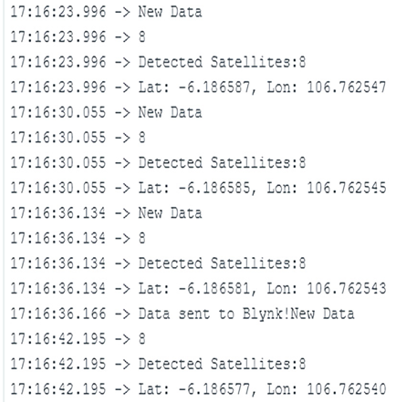
When the code is running, you will need to wait for a while for the NEO-6M GPS module to find the GPS satellites. You may need to bring the device outdoors so it can get better at receiving the satellite signals. If the GPS module is already receiving satellite signals, you may find a blinking LED inside the module. You’ll also receive information in the Serial Monitor regarding the number of satellite signals received by the module and the latitude and longitude location position. Please notice that once every 30 seconds, a message will appear in the console notifying that data was sent to Blynk. You can change the interval at which this message appears by changing the value of the sendPeriod variable.

Figure 13.18 – Output shown on the Arduino IDE Serial Monitor
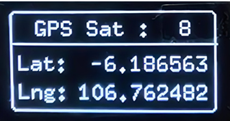
You will also can see the location coordinates and the number of GPS satellites read by the GPS module.

Figure 13.19 – Coordinates shown on the GPS module
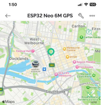
Additionally, the Blynk app will show the location of the device on a map, as in the following example, showing the GPS in Melbourne, Victoria, and Australia.

Figure 13.20 – Blynk app showing the device’s location
From the Blunk Dashboard on a Windows computer, we can also view the map by clicking on the ESP32 NEO-6M GPS device.
With that, we’ve managed to implement GPS tracking by utilizing the ESP32! Now, we can move on to looking at how we can work with industrial partners to ensure the success of our IIoT projects.