Setting up the hardware for the project – Developing IoT Solutions for Digital Transformation within Industry 4.0
By Patrice Duren / May 14, 2022 / No Comments / AWS Certification Exam, Case study of Amazon, IoT sustainability, Managing threats and risks
To start off with, we can wire up the hardware for the project:
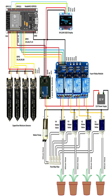
Wire up the necessary hardware according to Figure 13.22.

Figure 13.22 – Wiring diagram of a smart plant watering system
Connect the VCC and GND of the first capacitive soil moisture sensor to the 3V3 and GND pin of the ESP32. Connect the AUOT/Data pin of the sensor to the sensor1 pin of the ESP32S, that is, GPIO 36 (G36). Connect the other capacitive soil moisture sensors’ (sensor2, sensor3, and sensor4) VCCs and GNDs to the 3V3 and GND pins of the ESP32. Connect the AUOT/Data pins of the sensors to the G39 pin for sensor2, G34 for sensor3, and G35 for sensor4.
Connect the VCC and GND of the inputs of the four-port relay module to the 3V3 and GND of the ESP32. Connect pins IN1, IN2, IN3, and IN4 to pins G26, G27, G14, and G13, respectively.
Connect all the COM pins (the center pin of each relay output) to the +12V power supply. Connect the NO (which stands for Normally Open) pin of relay1 connected to the red wire of water valve 1, the NO pin of relay2 to the red wire of water valve 2, the NO pin of relay3 to the red wire of water valve 3, and the NO pin of relay4 to the red wire of water valve 4.
Connect the VCC and GND of the inputs of the one-port relay module to the 3V3 and GND of the ESP32. Connect the IN1 ping to the pump_relay pin (G32). Connect the COM port of the output of the one-port relay to the +12V power supply, and connect the NO port of the output of the one-port relay to the red cable (+) of the water pump. Next, connect the black cable (-) of the water pump to the (-)/ GND pin of the 12V power supply.
Using the silicon hose, connect one end to the intake outlet of the water pump (on the side), and put the other end into a bucket filled with water. Connect the outtake outlet (the middle one) to the input of the four-way splitter connector.
To each output of the four-port splitter connector, connect to the water intake of a solenoid water valve, while the outtake of the water valve goes to a plant pot through another piece of hose. You can adjust the length of each hose according to your needs.
With that, we have finished wiring up the hardware and can move on to setting up the necessary software.